


The long read: ‘We’re better off without standards’

Many factors are important in ballasting flat roof systems, such as wind speed and roof shape. In the past, however, wind force has unfortunately been underestimated, says wind expert Hans Ruscheweyh. pv magazine addressed this topic in a recent webinar with initiative partner Schletter, and drew several interesting points from the discussion.
From pv magazine 04/2020
Correct ballasting of rack-mounted flat-roof PV systems is about using as little weight as possible, but as much as necessary. Every extra kilogram on the roof reduces the probability that the system can be installed on a building with limited load reserves. But too little weight – and more importantly, too little ballast at crucial points – can cause a plant to shift in the wind or even lift off and take flight, causing catastrophic failure or becoming a safety hazard.
Seeking the right balance between too little, too much and just right, many market participants want clear guidelines, preferably in the form of a standard that specifies how ballast is calculated. After all, customers are often drawn to particularly light and inexpensive systems, while more robustly ballasted systems are at a disadvantage.
“I am glad that there’s no standard,” says Hans Ruscheweyh, voicing a dissenting opinion. Ruscheweyh is an industrial aerodynamics expert who offers consulting services and prepares wind assessments through his company, Ruscheweyh Consult. Until 1996, he was a professor at the RWTH Aachen University.
“As a standards body, you cannot foresee technical developments. Had we adopted a standard ten years ago, all of today’s installations would have been too heavy, and that would have slowed down the expansion of PV,” he says. This is a view not all aerodynamics experts share.
In a pv magazine webinar in September 2019 with initiative partner Schletter, Ruscheweyh explained that design changes between 2005 and 2015 had reduced the suction exerted by the wind on modules by a factor of 10. Ruscheweyh regularly prepares wind assessments for the company and has closely followed the development of roof mounting systems. In 2005 (in Germany), south-facing installations mounted at a 35-degree pitch were still common. These arrays offered the wind a significantly larger area of attack than the east-west systems commonly installed today at an inclination of 15 degrees or less. The design has also improved considerably, such that today well-designed systems have much less lift.
However, as there are no standards and technology is constantly changing, there is a great deal of uncertainty around where to turn for guidance. What follows are the answers to pressing questions posed by the webinar participants. Answering the questions were Hans Ruscheweyh and Mark Guntermann, an expert from the Dr. Cedrik Zapfe engineering office, which also works with Schletter.
What differences in wind conditions do we have to take into account when we consider flat roofs with and without photovoltaic systems?
Hans Ruscheweyh: Because there are no standards, installers of flat roof systems often used to assume the wind would behave the same on roofs with photovoltaics as on flat roofs without any superstructures. This would mean that the wind would first form a vortex at the edge of the building and then come back into contact with the roof. These zones of higher load at the edges and corners of buildings are identified in accordance with the German DIN standard and are more robust. Applying the zones to PV systems, however, can lead to fatal miscalculations. The actual distribution of load zones is quite different. The edge and corner zones defined in the DIN standard are much too small for PV systems and do not completely cover the heavily loaded zones. Using the flat roof as a model, you could fall victim to the misunderstanding that simply moving the system a little further towards the center of the roof would help. However, this does not change the loads on PV panels at all; to the contrary, the wind loads become even greater along the periphery of the PV system.
What is the effect of the mounting rack design?
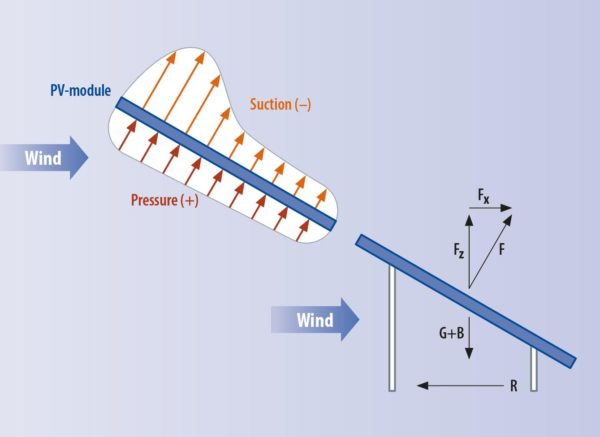
Modules positioned at an angle to the wind behave like aircraft wings. If a wind from the north comes into contact with a south-facing module, lift forms on the upper side and high pressure builds up underneath. These forces push the module upward and forward. However, suction on the top side of the panel is stronger at upper edge than at lower edge, so modules not only lift but also tilt. If the wind comes from the south-facing front of the panel, the module is pressed downward.
If the manufacturer adds a sloping panel that closes the open side, the suction generated by a north wind can be reduced, but only if a gap is left between the module and the wind deflector and only if this gap is properly designed. Only if the panel is as high as the module can some of the suction from the upper side get under the module and reduce lift. If the panel ends too soon at the top, the wind blows under the module and it can lift off. If the deflector is too short at the bottom, you have the same effect. If done correctly, the load can be cut in half for both corner modules and modules in the middle of the array. This reduces the ballast, but also increases the mounting costs and requires more material. Vertical closing surfaces are less favorable and here, too, there has to be a gap. The popular east-west arrangement, usually with an angle of five to 15 degrees, is even less susceptible to wind loads. This setup results in a lift coefficient of only 0.2, instead of 2.0 for a south-facing array with a steep angle of attack.
What has to be taken into account with regard to the layout of the array as a whole?
Spacing between the rows is key. It is determined by the angle of the sun in a south facing installation. At greater distances the wind load increases. Gaps increase the loads on the modules in the next row, because the wind is pulled down by the negative pressure on the last module before the gap. Even if there are steps in the roof, the first higher-lying element is again an edge element and has higher wind loads.
A mechanical connection between the modules in a row, as well as between a number of rows, creates a so-called “carrying effect”, known in mechanics as “effective width.” The wind forces are then distributed across the whole connected group and the necessary ballast weight is reduced.
When wind strikes the corner of a building, leading edge vortices are created on both facing sides. These fast-rotating vortices generate a high negative pressure and are responsible for the large loads at the edge of the building. Gusts of wind produce extreme localized wind loads that are significantly greater than the average, or “stationary” loads. These “unsteady loads” are especially crucial for module mounting, but they also have to be considered with regard to the supporting structure. They are limited to an effective area of three by three meters and can occur at any point in the system. The neighboring areas next to this nine square meter field may be loaded with the stationary forces, thus reducing ballast weight requirements for the group.
How do you calculate the wind load acting on a module and how is the ballast derived from it?
The wind load is calculated from the cp value; that is, the aerodynamic coefficient, times the surface area and the dynamic pressure. The wind force acts perpendicularly to the module surface (see diagram), whereas, if the wind comes from behind, it creates suction. This is divided into a vertical component, responsible for uplift, and a horizontal component, responsible for displacement. The uplift is counteracted by the weight of the system and the ballast weight. Together, these must be greater than the vertical lift force.
Friction counteracts sliding. If the friction is greater than the horizontal wind force, the array stays put. The frictional force results from the difference of the total weight and the lift force times the friction factor between the module racking and the roof cladding. Since this is the difference between large numbers, a slight increase in the lifting force can significantly reduce the friction force, causing shifting to occur. Therefore, it is very important that the wind force is determined correctly. This is where calculating the ballast gets fiddly.
At this point, the roof cladding material also has to be considered. It determines the friction factor in connection with the mounting system. This factor can only be determined experimentally. It should be noted that the roof cladding may be wet and that vibration in strong winds means that sliding friction, not static friction, is the decisive factor.
Is it permissible to deviate from the design and reduce the weight of the installation and the ballast? In what context is this possible?
Hans Ruscheweyh: There are determining factors, such as the wind and terrain category, which can be changed if there are good reasons for doing so – if, for instance, a higher neighboring building creates a wind shadow. However, this has to be considered on a case by case basis. Interference can also have adverse effects and lead to higher wind speeds. When I am presented with a PV plant and I am familiar with the surrounding buildings, I can tell from my experience what to do. If it gets complicated, we have to test the design in a wind tunnel.
Mark Guntermann: Another point is that operators can make decisions that can reduce the ballast requirement. For example, wind-resistance designs are always calculated for a period of 50 years and designed around events that occur statistically during that period. However, if the plant will only be in operation for 25 years, fewer strong wind events will occur, statistically speaking. In this case we can apply the cprob probability factor. For the PV plant, this means about 4% less dynamic pressure purely on the basis of wind statistics. In addition, the operator can decide to choose a more frequent maintenance schedule. If he does maintenance twice a year and walks the roof, it’s enough to convince the insurance company to set a lower property damage class. This can reduce the ballast by up to 10%. Of course, this means higher maintenance costs.
There are two groups of manufacturers – those with low ballast specifications and those with high ballast specifications. Which values are being adjusted by those with low ballast calculations?
Hans Ruscheweyh: There are several influencing factors: wind load, friction factor, and group effect. These are the key factors and interventions in special installations. There are people who assume a friction factor of 0.8. That is playing it a bit fast and loose, because such a high friction factor does not occur in reality. The only way to see this, however, is to look at the input values. You also have to estimate the terrain category, for instance. There are situations on the outskirts of a city or in the city center, so you can choose between two options – or think of the effect of the landscape on a hillside or at a landfill. There, the wind is accelerated, and this can be taken into account with an orographic factor. If the designers recognize the situation correctly and take it into account, the loads can easily double.
What is the influence of a parapet that is, say, 30 to 40 centimeters high?
The parapet is an important topic. But mostly it exists for structural reasons. A parapet height of 30 centimeters does not have a significant effect on wind loads. As it gets higher, starting at 60 to 80 centimeters, the wind loads on the elements of the PV system change. If the parapet is relatively close to the PV array, the first row is subject to lower wind loads. However, due to the curling of the edge vortex, the wind exerts higher loads on the second, third and fourth module rows – the load shifts to the rear. Which rows are affected depends on the height of the parapet. In any case, the parapet does not provide much protection, and it has to be considered in relation to the roof height. Since the wind loads on high buildings increase somewhat, a parapet of one-meter height on a five-meter-high building can be considered differently than the same parapet on a 50-meter-high building.
As long as we have no German standards for flat roof ballasting, can we fall back on the American standard?
I’m skeptical about that. The U.S. standard is very complicated. If you use it to design south-facing installations, you can get something useful out of it. In many other areas, the results are not cost-effective. In my opinion, the Americans did not take the wind shadow in the center of large arrays into account in the experiments with rearward elements. As a result, they calculate ballast values that are too high.
By Michael Fuhs/Cornelia Lichner